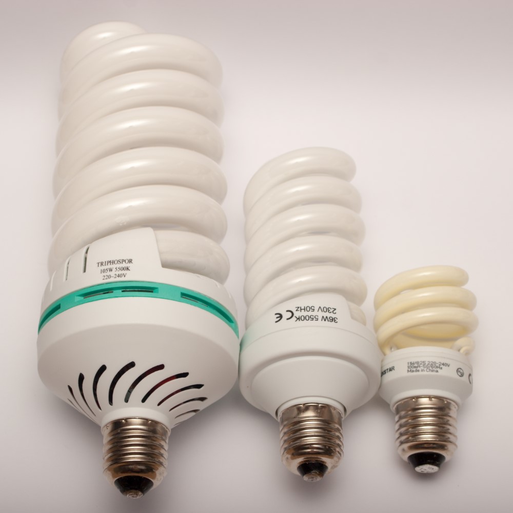
CFL Manufacturing Process and History
Compact fluorescent lamps (CFL) were intended to replace light bulbs. This fluorescent light utilizes a tube that is bent to fit into a globule and a reduced electronic counterbalance in the base of the lamp.
CFLs Working Principle
CFL utilizes one-fifth to 33% the electric power and last eight up to fifteen times longer. A CFL has a higher price tag than a light bulb because it spares more than five times its price tag in power costs over light’s lifetime. Like every fluorescent light, CFLs contain lethal mercury that facilitates an electro-counter balance and transfer.
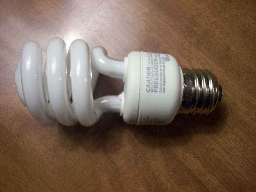
In numerous nations, governments restrict the transport of CFLs together with standard waste. Such nations set up uncommon accumulation frameworks for CFLs and other different dangerous waste. The task policy carries on as in other fluorescent lighting; electrons that are bound to mercury particles are more nimble to states where they will emanate bright light as they come back to a lower vitality level.
This produced bright light is changed over into ‘light’ as it strikes the fluorescent covering and additionally into heat when consumed by different materials like glass, which is why CFLs emanate a phantom power. CFL light dissemination is not quite the same as that of light bulbs.
CFLs vs Light Bulbs
Phosphor details enhance the apparent shade of the light transmitted by CFLs. It however has no end goal as a few sources rate the best “delicate white” CFLs as subjectively comparative in lighting to standard light bulbs.
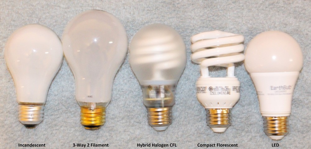
White LED lights currently rival CFLs for high-proficiency lighting and General Electric is ceasing the creation of local CFL lights for LED lights.
History of CFLs and their Manufacturing Process
Peter Cooper Hewitt created the threshold to the innovative fluorescent light. The Cooper Hewitt lights were utilized for photographic studios and industries in the late 1890s. Edmund Germer, Friedrich Meyer, and Hans Spanner generated a high-weight vapor light in 1927. George Inman later collaborated with General Electric to make a useful fluorescent light, sold in 1938 and licensed in 1941.
Circular and U-molded lights were conceived to reduce the length of fluorescent light apparatuses. The principal fluorescent light and apparatus were shown at the 1939 New York World’s Fair. Edward E. Mallet, an architect with General Electric due to the 1973 oil crisis, developed the round CFL in 1976.
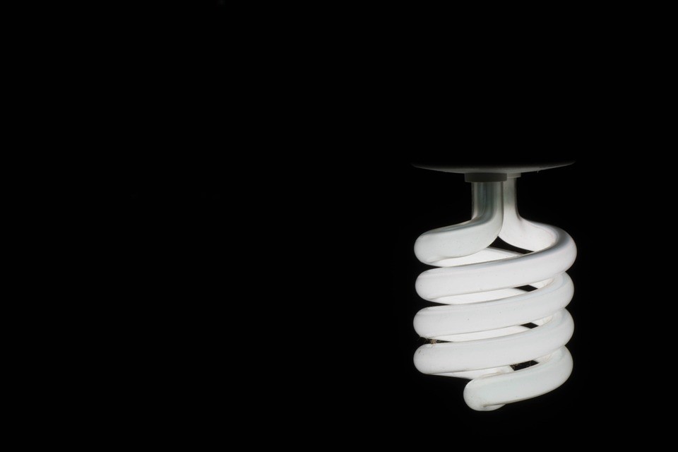
Although the outline met its objectives, it would cost GE about $25 million to assemble new processing plants to create the lights, and in this forecasted development was shelved. The plan was in the long run replicated CFLs. In 1995, helical CFLs, made in China, turned out to be of value economically. Since then their deals relentlessly expand.
Philips offered its typical SL, which was a pike mount light with an outstanding ballast in the early 1980s. The light utilized a collapsed T4 tube, stable tri-shading phosphors, and a mercury amalgam. This was the main fruitful fasten substitution for a brilliant light. In 1985, Osram began offering its model EL light, which was the primary CFL to incorporate an electronic ballast.
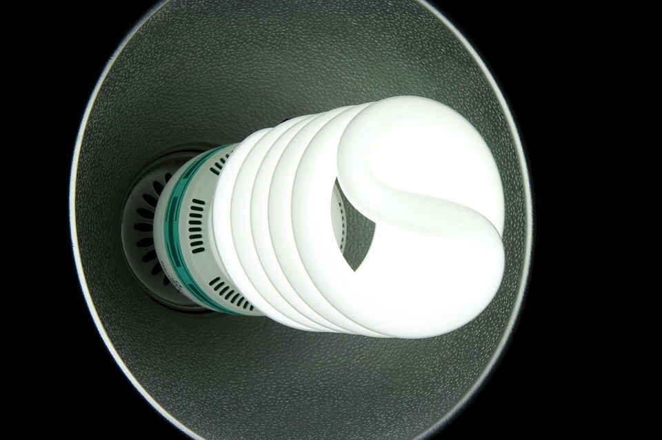
Advancement of fluorescent lights that could fit in an indistinguishable volume from equivalent glowing lights required the improvement of new, high-adequacy phosphors that could withstand more power per unit territory than the phosphors utilized as a part of more seasoned, bigger fluorescent tubes.
In mid-2016, General Electric declared the waste of CFL creation in the United States. Driven costs were dropping, falling admirably beneath $5 for an essential knob in 2015. Thus, clients had been moving toward LEDs. CFLs were likewise confronting the likelihood of proposed directions for 2017 that would make trouble fitting the bill for the Energy Star rating
CFL Manufacturing Process
There are two kinds of CFLs
-
Coordinated CFLs
Coordinated lights join the tube and stabilizer in a solitary unit. These lights enable you to supplant brilliant lights effortlessly with CFLs. Coordinated CFLs function admirably in numerous standard glowing light installations, lessening the cost of changing over to fluorescent. 3-way lights and dimmable models with standard bases are accessible.
-
Non-coordinated CFLs
Since the weights are put in the light installation, they are bigger and last longer contrasted with the coordinated ones, and they do not should be supplanted when the tube achieves its finish of-life.
Non-coordinated CFL lodgings can be both more costly and complex. They have two sorts of tubes:
- A bi-stick tube– Intended for customary stabilizer
- Quad-stick tube– Intended for an electronic counterweight or a traditional counterbalance with an outer starter.
A bi-stick tube contains a coordinated starter, which forestalls the requirement for outside warming pins however causes contrariness with electronic counterbalances. Non-coordinated CFLs can likewise be introduced to a traditional light installation utilizing a connector containing an inherent attractive counterbalance. The connector comprises of a normal globule screw, the stabilizer itself and a clasp for the light’s connector.
CFLs have two primary segments:
- An attractive or electronic stabilizer
- Gas-filled tube
Electronic counterweights contain a little circuit board with an extension rectifier, a channel capacitor and generally, two exchanging transistors, which are regularly protected, door bipolar transistors. The approaching AC current is first redressed to DC, at that point changed over to high recurrence AC by the transistors, associated as a full arrangement DC to AC inverter.
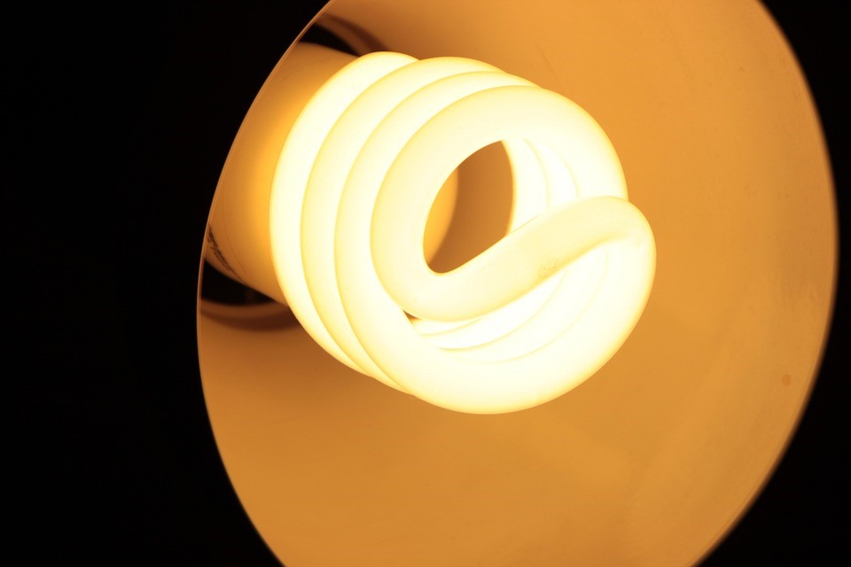
The subsequent high recurrence is connected to the light tube. Since the thunderous converter has a tendency to settle light present over a scope of information voltages, standard CFLs don’t react well in diminishing applications and will encounter a shorter life expectancy and once in a while calamitous disappointment. Extraordinary electronic counterweights
Some CFLs are marked not to be run base up, since warmth will abbreviate the stabilizer’s life. Such CFLs are inadmissible for use in pendant lights and particularly unacceptable for recessed light installations. CFLs intended for use in such installations are available.
Future of CFLs
Current proposals for completely encased, unventilated light apparatuses, for example those recessed into protected roofs are either to utilize “reflector CFLs”, frosty cathode CFLs or to supplant such apparatuses with those intended for CFLs. A CFL will flourish in zones that have great wind stream, for example, in a table lamp.
